Underfloor Heating Manifolds: What They Do and How They Work
Ready to start your project? Find qualified underfloor heating installers through the Underfloor Heating Directory, plan your next step at the Underfloor Heating Directory homepage, or explore more practical guidance at underfloorheating.info.
Guided reading
Not sure where to start?
Answer three quick questions and we will point you to the right guides for your project.
Find your starting pointThree questions. About 30 seconds. No sign-up.
The manifold controls every wet underfloor heating system. It may look complicated, but the valves, gauges and actuators simply distribute hot water between individual zones and give you room-by-room temperature control. If you're installing, maintaining or troubleshooting wet UFH, you need to know how this part works and how to size it.
I'll take you through the basics first, then cover balancing, sizing and fault finding.
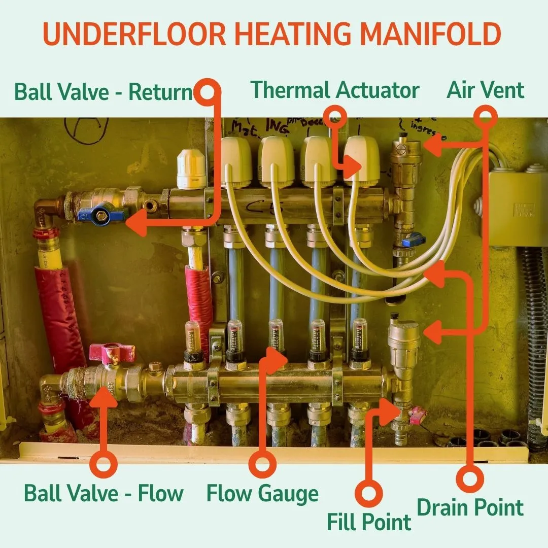
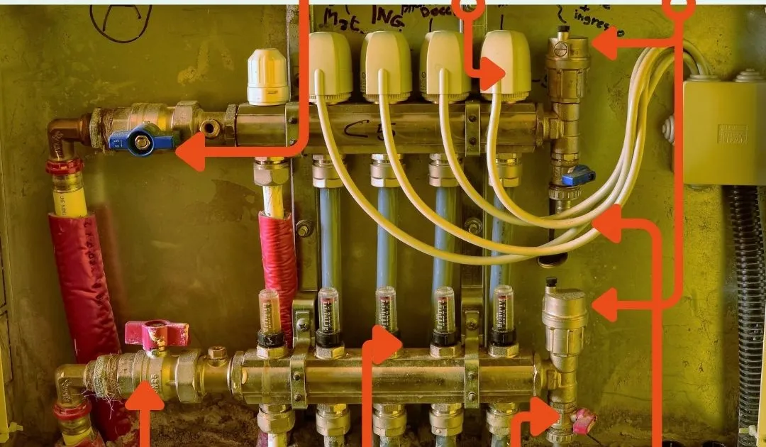
What this diagram shows (left to right, top to bottom):
- Ball valve – return: manual shut-off on the return bar, isolates the whole manifold for maintenance.
- Thermal actuators: one per zone, on top of the return bar, these are the motorised valves that open and close each room's circuit.
- Air vent: bleed point for trapped air, usually at the end of the flow bar.
- Ball valve – flow: manual shut-off on the flow (supply) bar.
- Flow gauges (also called flow meters, or rotameters): one per zone, showing live flow rate in litres/minute, the main tool used for balancing. This guide uses "flow gauge," but you'll see the same component called a flow meter elsewhere.
- Fill point: connection used to fill and pressurise the system during commissioning.
- Drain point: connection used to drain the manifold for maintenance or replacement.
How does an underfloor heating manifold work?
An underfloor heating manifold takes hot water from a boiler or heat pump and splits it between separate pipe loops, one per room or zone. Each zone has its own actuator and flow gauge on the manifold, so a thermostat can open or close that zone's valve independently while the others keep running. Water leaves via the flow bar, passes through the floor loop giving up its heat, and comes back cooler through the return bar to be reheated. This is what allows one wet underfloor heating system to give every room its own temperature.
Manifold explained in 60 seconds
- What it is: A small metal assembly that splits hot water from your boiler or heat pump into multiple floor circuits.
- Why it matters: One manifold controls every room independently via flow meters and actuators.
- Flow side (top): Hot water in → flow meters → each circuit.
- Return side (bottom): Cooler water back from each circuit → return to heat source.
- Actuators: Tiny motorised valves that open/close each zone on demand.
- Blending valve: Mixs hot boiler water with cooler return water to hit the right UFH temperature (35–50°C).
- Pump: Pushes water through the loops.
Jump to full component guide ↓
New to wet underfloor heating? Start with our Complete Wet UFH Guide for system fundamentals, or see our How Does Underfloor Heating Work guide to understand the basics first.
What Is an Underfloor Heating Manifold?
A manifold takes hot water from your boiler or heat pump and divides it between multiple heating zones, typically individual rooms or areas. Think of it as a roundabout for water: one way in from the heat source and several ways out to the rooms.
The Core Functions
1. Water Distribution
- Receives hot water from single heat source
- Divides flow between multiple pipe loops
- Each loop serves one zone/room
- Returns cooler water back to heat source
2. Independent Zone Control
- Each zone controlled by dedicated actuator
- Actuators open/close valves based on thermostat demand
- Zones heat independently
- Unoccupied rooms don't consume energy
3. Flow Balancing
- Adjustable flow rate for each zone
- Ensures correct heat output per room
- Compensates for different loop lengths
- Optimises system efficiency
4. System Monitoring
- Flow meters show water circulation per zone
- Temperature gauges monitor system operation
- Pressure indication
- Visual confirmation of system status
5. Maintenance Access
- Central location for air bleeding
- Isolation valves for individual zones
- Easy actuator replacement
- Diagnostic point for problems
Why Manifolds Are Essential
Without a manifold:
- Cannot have multiple independently controlled zones
- Cannot balance different loop lengths
- Difficult to isolate individual zones
- No visual indication of system operation
- Complex to commission and maintain
With a properly specified manifold:
- Room-by-room temperature control
- Optimal comfort and efficiency
- Easy troubleshooting
- Simple maintenance
- Professional, organized installation
Manifold Components Explained
Know what each component does and you'll find it much easier to diagnose faults, commission the system and explain a problem to a heating engineer.
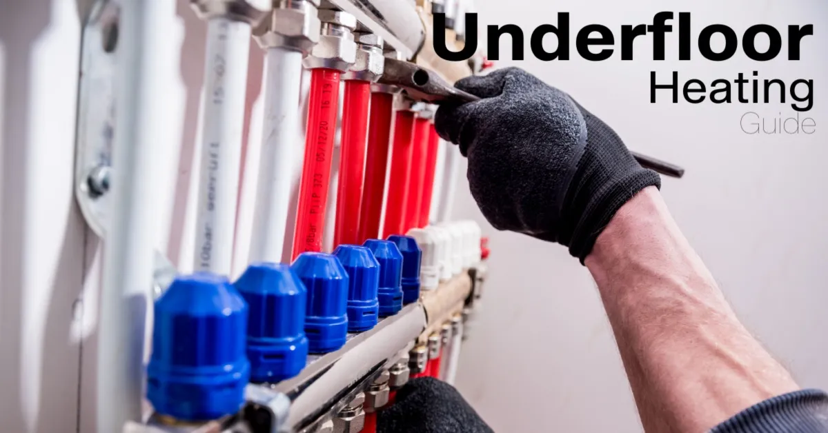
Flow Bar (Supply Side)
The flow bar is the assembly that distributes hot water to each zone. Depending on the manifold model and how it's mounted, this can be the top or bottom bar, check your unit's labelling rather than assuming a fixed position.
Key Components on Flow Bar:
1. Inlet Connection
- Typically 1" BSP or 3/4" BSP
- Connects to blending valve output
- Hot water entry point (35-50°C)
- Usually positioned on left end
2. Flow Meters (Rotameters)
- Clear plastic cylinders with floating indicator
- Shows real-time flow rate in litres/minute
- Adjustable cap to set target flow
- Essential for balancing system
- Typical range: 0.5-4 L/min
How Flow Meters Work:
- Water flow lifts internal float
- Float position indicates flow rate
- Reading scale calibrated in L/min
- Higher float = more flow
- Adjust top cap to restrict or increase flow
3. Isolation Valves
- Manual shut-off for each zone
- Allows individual loop isolation
- Useful for maintenance or repairs
- Ball valve or gate valve design
- Lever or screw adjustment
4. Air Vents
- Automatic or manual bleed points
- Releases trapped air from system
- Usually one per 2-4 zones
- Critical for preventing airlocks
- Manual vents require annual bleeding
5. Drain/Fill Points
- Allow system draining for maintenance
- Located at flow bar ends
- Standard hose connection
- Used during commissioning
Return Bar (Return Side)
The return bar collects cooler water from each zone and returns it to the heat source. It sits opposite the flow bar, top or bottom depending on the model.
Key Components on Return Bar:
1. Zone Connections
- One connection per heating loop
- Typically 16mm or 20mm push-fit
- Secure pipe coupling system
- Labelled for identification
2. Actuators (Thermostatic Heads)
- Motorised valve operators
- One per zone
- Controlled by zone thermostat
- Opens/closes valve when zone calls for heat
- 24V or 230V operation
Actuator Operation:
- Thermostat satisfied: Valve closes, no flow
- Thermostat calling: Actuator opens valve
- Motorised pin pushes valve open
- Visual indicator shows valve position
- Typically takes 2-3 minutes to fully open/close
3. Return Temperature Sensors
- Measure water temperature leaving zone
- Useful for system diagnostics
- Confirms zone is circulating
- Helps identify problems
- Not always fitted on basic manifolds
4. Balancing Valves
- Fine-tune flow to each zone
- Work in conjunction with flow meters
- Typically lockshield type (prevents accidental adjustment)
- Set during commissioning
- Rarely need adjustment once set
5. Return Outlet
- Collects water from all zones
- Returns to blending valve
- Typically cooler than flow (5-10°C drop)
- Usually positioned on right end
- Same size as flow inlet (1" or 3/4" BSP)
Blending Valve (Mixing Valve)
The blending valve is crucial but often misunderstood. It protects your UFH system from excessive temperatures.
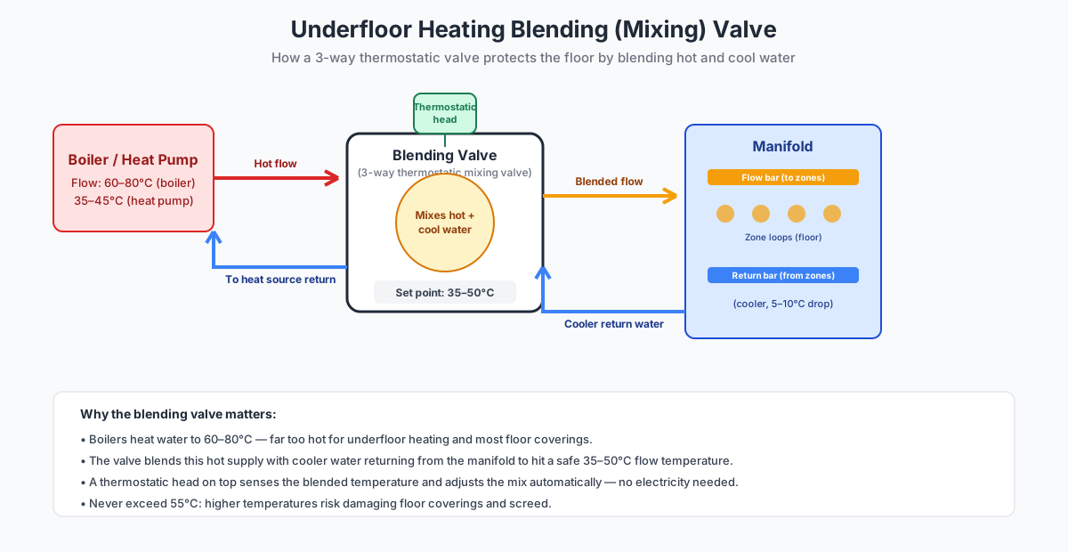
What this diagram shows: hot water from the boiler or heat pump (60–80°C, or 35–45°C for a heat pump) enters the blending valve, where a thermostatic head mixes it with cooler water returning from the manifold. The blended output, set between 35–50°C, feeds the manifold's flow bar, while the manifold's own return feeds back into the valve's cool inlet, completing the loop.
Why Blending Valves Are Essential:
- Boilers heat to 60-80°C (too hot for UFH)
- UFH requires only 35-50°C
- Floor coverings damaged above 50°C
- Mixing valve blends hot boiler water with cooler return water
- Achieves safe, optimal temperature
Blending Valve Operation:
1. Thermostatic Head
- Senses water temperature
- Automatically adjusts mixing ratio
- Maintains set point (e.g., 40°C)
- Mechanical operation (no electricity)
2. Three-Way Valve Body
- Hot water input (from boiler)
- Return water input (from manifold)
- Mixed water output (to manifold)
- Proportional mixing
3. Flow Temperature Setting
- Adjustable dial (typically 20-80°C range)
- Set to 35-50°C for UFH
- Lower for heat pumps (35-40°C)
- Higher for design heat load days
Typical Settings:
- Heat pump systems: 35-40°C
- Gas boiler, good insulation: 40-45°C
- Gas boiler, poor insulation: 45-50°C
- Never exceed: 55°C (floor covering protection)
Pump and Wiring Centre
These components complete the manifold assembly.
Circulation Pump:
- Typically 40-80W low-energy pump
- Adjustable speed settings (I, II, III)
- Overcomes pipe resistance
- Maintains circulation through loops
- Quiet operation essential
Wiring Centre (Control Box):
- Houses electrical connections
- Links thermostats to actuators
- Powers circulation pump
- Boiler/heat pump call signal
- Typically 24V or 230V system
Manifold Cabinet:
- Protective enclosure for all components
- Wall-mounted or recessed
- Lockable door for safety
- Ventilation for heat dissipation
- Cable entry points
Refer back to the labelled diagram above: the flow bar (with ball valve, flow gauges and thermal actuators) sits opposite the return bar (isolation and drain points).
For complete system operation details, see our How Does Underfloor Heating Work guide.
How Manifolds Control Multiple Zones
Once you understand the sequence, troubleshooting and improving performance become much easier.
The Control Sequence
Step 1: Thermostat Calls for Heat
- Room temperature drops below set point
- Zone thermostat closes relay
- Signal sent to wiring centre
- Wiring centre activates corresponding actuator
Step 2: Actuator Opens
- Motor in actuator engages
- Pushes pin down on valve
- Valve gradually opens (2-3 minutes)
- Visual indicator rises (shows valve open)
- Water can now flow to that zone
Step 3: Pump Activates
- Wiring centre detects open zone
- Sends signal to circulation pump
- Pump begins running
- Creates pressure to circulate water
- Indicator light shows pump operation
Step 4: Boiler/Heat Pump Fires
- Wiring centre sends call for heat to heat source
- Boiler/heat pump begins heating water
- Water temperature rises to set point
- Blending valve regulates temperature
Step 5: Water Circulates
- Hot water enters manifold flow bar
- Passes through flow meter (reading shows)
- Enters pipe loop for that zone
- Travels through floor, giving up heat
- Returns via return bar, cooler
Step 6: Heat Transfer
- Pipe transfers heat to screed
- Screed warms floor surface
- Floor radiates heat to room
- Room temperature rises
Step 7: Thermostat Satisfied
- Room reaches target temperature
- Thermostat opens relay
- Signal to wiring centre stops
- Actuator begins closing
Step 8: Actuator Closes
- Motor reverses or spring returns
- Pin releases, valve closes
- Visual indicator lowers (shows valve closed)
- Flow stops to that zone
- Flow meter reading drops to zero
Step 9: Other Zones May Continue
- Different zones operate independently
- Some may still be heating
- Pump continues while any zone open
- Boiler continues firing if demand exists
Step 10: All Zones Satisfied
- All actuators closed
- No zones demanding heat
- Pump stops after short delay (typically 3-5 minutes)
- Boiler/heat pump stops firing
- System enters standby
Zoning Benefits
Independent zone control via manifolds provides:
- Energy savings: Only heat occupied rooms (15-30% typical savings)
- Comfort: Different temperatures suit different rooms
- Flexibility: Schedules vary by room (bedrooms heat later, living areas earlier)
- Efficiency: No wasted heat in unoccupied spaces
For detailed zoning strategies, see our Underfloor Heating Zoning Guide.
Types of Manifolds
Manifolds come in various configurations to suit different system sizes and budgets.
By Number of Ports
2-Port Manifolds
- Smallest configuration
- Two independent zones
- Compact size
- Limited expansion
- Budget option
Typical use: Small flat, bathroom + kitchen
4-Port Manifolds
- Most common for small homes
- Four independent zones
- Good balance of price and functionality
- Suitable expandability
Typical use: 2-3 bedroom house (living room, kitchen/dining, 2x bedrooms grouped)
6-Port Manifolds
- Popular for larger homes
- Six independent zones
- Comprehensive control
- Professional standard
Typical use: 3-4 bedroom house (living room, kitchen, dining room, master bedroom, other bedrooms, bathrooms)
8-Port & 10-Port Manifolds
- Large properties
- Maximum flexibility
- Can combine multiple manifolds if needed
- Professional specification
Typical use: Large houses, multi-zone open plan areas
12-Port Manifolds
- Very large or complex systems
- Multiple floors
- High-end installations
- Maximum control
By Features
Basic Manifolds
- Flow meters
- Manual valves
- Simple design
- Budget-friendly
Standard Manifolds
- Flow meters with adjustment
- Automatic air vents
- Drain/fill points
- Actuator-ready
Premium Manifolds
- Temperature gauges (flow and return)
- Ball valves for easy isolation
- Pre-assembled with pump
- Integrated blending valve
- Wiring centre included
- Complete "plug and play" solution
Smart Manifolds
- Electronic flow control
- Digital display
- Remote monitoring
- App integration
- Advanced diagnostics
- Weather compensation
By Pipe Connection Type
Compression Fittings
- Traditional connection method
- Reliable and proven
- Requires wrench for installation
- Easy to identify pipe runs
Push-Fit Connections
- Quick installation
- No tools required
- Popular in modern systems
- Secure and reliable
Euro Cone Connections
- Professional standard
- Very secure
- Requires special tool
- Clean, professional appearance
Manifold Sizing and Selection
Get the manifold size wrong and the whole system will struggle. Here's how to choose it properly.
How Many Ports Do You Need?
Count your zones:
- Each separately controlled room = 1 port
- Large rooms may need 2 ports (>20m²)
- Small adjoining rooms can share 1 port
Add contingency:
- Always specify 1-2 spare ports
- Allows future expansion
- Provides redundancy
- Minimal cost difference
Example Calculation:
3-bedroom house:
- Living room: 1 port
- Kitchen/dining: 1 port
- Master bedroom: 1 port
- Bedroom 2: 1 port
- Bedroom 3: 1 port
- Bathroom/en-suite: 1 port (can share)
Total: 6 ports

Recommendation: 8-port manifold (2 spare)
Flow Rate Requirements
Calculate total flow rate:
Each zone requires specific flow based on:
- Pipe spacing (closer spacing = more flow)
- Loop length
- Heat output required
Typical flow rates:
- 100mm pipe spacing: 2.0-2.5 L/min per loop
- 150mm pipe spacing: 1.5-2.0 L/min per loop
- 200mm pipe spacing: 1.0-1.5 L/min per loop
- 300mm pipe spacing: 0.5-1.0 L/min per loop
Total flow = Sum of all loops
Example:
- 6 zones @ 1.5 L/min each = 9 L/min total
- Choose manifold and pump rated for ≥9 L/min
Pump Sizing
Head (Pressure) Calculation:
- 0.5-1.0m head per 100m of pipe
- Add 2-3m for manifold and fittings
- Add heat source and blending valve resistance
Flow Rate:
- Must meet total flow requirement
- Adjustable speed pumps provide flexibility
- Typically class A energy rated (low consumption)
Example:
- Total pipe: 400m
- Head required: 4m (pipe) + 3m (components) = 7m
- Flow required: 9 L/min
- Select: Pump rated 10 L/min @ 7m head
For complete system design guidance, see our UFH Design & Planning Guide.
Material and Quality
Manifold Bar Material:
Brass:
- Traditional choice
- Corrosion resistant
- Heavy duty
- Premium option
Stainless Steel:
- Modern standard
- Superior corrosion resistance
- Lighter weight
- Contemporary appearance
Coated Steel:
- Budget option
- Adequate for most applications
- Check coating quality
- May not last as long as brass/stainless
Actuator Quality:
Budget Actuators:
- Basic on/off operation
- 230V typically
- 2-3 minute actuation
- 5-10 year lifespan
Quality Actuators:
- Smooth, quiet operation
- 24V (safer)
- 2-3 minute actuation
- 10-15 year lifespan
- Replaceable without draining system
Premium Actuators:
- Modulating (proportional) control
- Very quiet operation
- Position feedback
- 15+ year lifespan
- Advanced control compatibility
Manifold Installation and Positioning
Correct installation ensures optimal performance and easy maintenance.
Location Requirements
Accessibility:
- Must be easily accessible for maintenance
- Annual bleeding required
- Actuator replacement accessibility
- Flow meter adjustment access
Typical Locations:
- Utility room
- Understairs cupboard
- Plant room
- Dedicated manifold cupboard
- Airing cupboard (if temperature suitable)
Avoid:
- Difficult-to-reach lofts
- Areas prone to freezing
- Extremely hot locations (near boiler)
- Damp areas
Height and Positioning
Optimal Height:
- 500-1000mm above floor level
- Easy viewing of flow meters
- Comfortable working height
- Above expected water level (flooding protection)
Orientation:
- Flow bar at top, return bar below
- Clearly label which is which
- Inlet/outlet on same side for neat pipework
- Allow space for actuator installation
Clearances:
- 300mm above manifold (actuator installation)
- 150mm below manifold (pipe bending radius)
- 200mm either side (access for maintenance)
- 500mm in front (comfortable working space)
This applies just as much to a retrofit as a new build, including milled screed (in-cut) retrofits that cut pipe channels directly into an existing concrete or screed floor. The manifold itself doesn't change: it still needs a wall-mounted cabinet meeting the clearances above, regardless of how the pipe below reaches it.
Pipework Connections
Best Practices:
1. Support Manifold Securely
- Use proper brackets (included with quality manifolds)
- Fix to solid wall or dedicated frame
- Multiple fixing points
- Support weight when full of water
2. Label All Pipes
- Mark each zone clearly
- Use adhesive labels or tags
- Include room name
- Update if system modified
3. Insulate Pipework
- Insulate feed and return pipes to manifold
- Reduces heat loss
- Prevents condensation
- Maintains temperature
4. Install Isolation Valves
- Before and after manifold assembly
- Allows manifold removal without draining entire system
- Essential for maintenance
- Ball valves preferred for full-bore flow
5. Pressure Testing
- Test before covering pipes
- 2x operating pressure for 24 hours
- Check all connections for leaks
- Document test results
Electrical Connections
Wiring Centre Position:
- Adjacent to manifold
- Protected from water
- Clear cable routes
- Adequate ventilation
Safety Requirements:
- Qualified electrician must install
- Correct cable sizing
- RCD protection
- Earth bonding
- Cable glands for neat entry
For complete installation guidance, see our DIY UFH Installation Guide.
How to Connect an Underfloor Heating Manifold to a Boiler
The manifold never connects directly to a boiler's flow and return, the temperatures involved are too different, and doing so would overheat the floor. The connection always runs through a blending valve (see Blending Valve above), which sits between the boiler and the manifold.
The typical sequence is:
- Boiler flow and return connect to the blending valve's hot and return inlets.
- The blending valve mixes boiler-hot water (60–80°C) with cooler water returning from the manifold to produce a safe UFH flow temperature (35–50°C).
- The blended output feeds the manifold's flow bar inlet.
- The manifold's return outlet feeds back to the blending valve's return input, completing the loop back to the boiler.
- Isolation valves are fitted on both sides of this connection so the manifold assembly can be isolated and removed without draining the whole heating system.
- A circulation pump, either integrated into a premium manifold or fitted separately, provides the flow to overcome the resistance of the UFH loops, since the boiler's own pump is usually sized for radiator circuits, not the smaller-bore, higher-resistance pipework of UFH.
If the manifold is feeding a system that also has radiators (a common setup in retrofits. UFH downstairs, radiators upstairs), the blending valve and manifold sit on their own branch off the boiler, independent of the radiator circuit, so each can run at its own temperature. Always have this connection made or checked by a qualified heating engineer, it involves both plumbing and, for the pump and wiring centre, electrical work covered by Part P (see our UK building regulations guide).
Underfloor heating manifold wiring diagram
The diagram below shows the full picture: room thermostats wired back to a central wiring centre, which switches the actuators on the manifold and calls for heat from a zone valve on the boiler, the same sequence described in How Manifolds Control Multiple Zones above, laid out as a single wiring schematic.
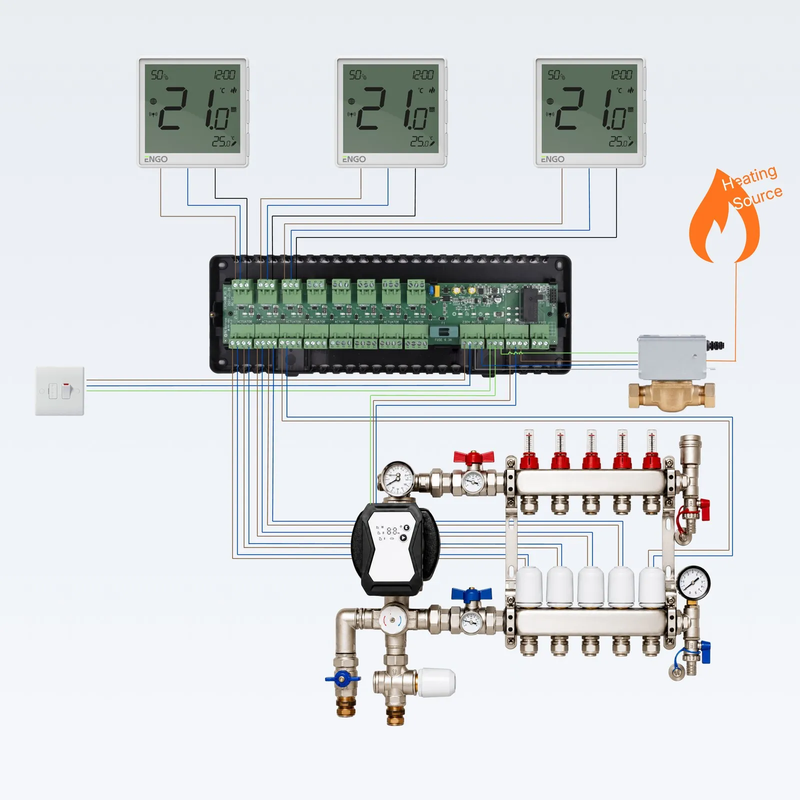
What's shown: three room thermostats (top) wire back to the wiring centre, which distributes power and switching signals to each zone's actuator on the manifold. The wiring centre also sends a call-for-heat signal to a zone valve on the boiler ("Heating Source"), which opens to supply the blending valve and pump assembly feeding the manifold's flow bar. Wire colours and terminal layout vary by manufacturer, always follow the wiring diagram supplied with your specific wiring centre and thermostats rather than this one alone.
Download this wiring diagram as a PDF, useful to keep on site during installation or to hand to your electrician.
For electric UFH wiring, thermostat terminal layouts, RCD requirements and common wiring faults across both system types, see our dedicated underfloor heating wiring diagrams guide.
How to Hide an Underfloor Heating Manifold
A manifold cabinet doesn't have to be visible. The clearances covered earlier in this guide (300mm above, 150mm below, 200mm either side, 500mm in front) apply regardless of how it's concealed, the goal is to hide the cabinet, not remove the access it needs.
Common concealment options:
- Recessed cabinet: the manifold sits inside a stud wall with only a flush-fitting access door visible, the neatest option, but needs planning before the wall is built.
- Cupboard integration: mounted inside an existing understairs cupboard, airing cupboard, or utility room unit, behind a normal door. The cheapest retrofit option if you already have suitable cupboard space nearby.
- Purpose-built surface cabinet: a lockable enclosure fixed to the wall and boxed in or painted to match the room, straightforward to retrofit, though it does protrude from the wall.
- False wall or stud partition: a shallow false wall built in front of the manifold with an access hatch, used where there's no existing cupboard and a recessed cabinet isn't practical.
- Behind a picture or mirror on a magnetic/hinged panel: a decorative option for a manifold in a hallway or living space, provided the hinge mechanism still allows full access.
Whichever option you choose, keep the location on your list of "don't forget" items when redecorating, a manifold that's been fully boxed in without a properly sized, easily removable access panel is a common cause of expensive call-outs when a heating engineer can't reach it for the annual bleed.
Underfloor Heating Manifold Pump: Sizing and Settings
The circulation pump is what actually moves water through the loops, sizing it correctly matters as much as sizing the manifold itself. Undersized, and distant zones will never reach their target flow rate no matter how the flow gauges are adjusted; oversized, and the system runs noisy and wastes energy.
Sizing basics (see the full worked examples in Manifold Sizing and Selection above):
- Flow rate: the pump must deliver at least the sum of every zone's target flow rate, for a typical 6-zone home this is usually in the 8–15 L/min range.
- Head (pressure): allow roughly 0.5–1.0m of head per 100m of pipe, plus 2–3m for the manifold and blending valve, plus the resistance of the heat source itself.
- Energy rating: modern manifold pumps are typically 40–80W, Class A energy rated, with adjustable speed settings (commonly labelled I, II, III, or shown as a percentage on electronic models).
Setting the pump speed:
- Commission and balance the system on the pump's highest speed setting first (see Balancing and Commissioning above).
- Once every zone reaches its target flow rate, step the pump down one speed setting at a time.
- Recheck flow gauges at each new setting, if any zone drops below target flow, go back up one step.
- Settle on the lowest speed setting that still holds every zone at its target flow. This is almost always quieter and more energy-efficient than leaving the pump on maximum.
A pump that's noisy at every speed setting, or that can't maintain flow even at maximum, usually means it's undersized for the system, see Common Manifold Problems below for diagnosis, or Upgrading and Replacing Manifolds for replacement guidance.
Manifold Valves Explained
A manifold typically has three distinct types of valve, each doing a different job, worth knowing apart when discussing a system with an installer or diagnosing a problem.
- Isolation valves (ball valves): manual on/off valves at the ends of the flow and return bars, and often either side of the whole manifold assembly. Used to shut off the entire manifold, or a section of it, for maintenance. Ball valves are preferred for these because they give full-bore flow when open.
- Actuator valves: the motorised valves on each zone connection, opened and closed automatically by the wiring centre in response to each zone's thermostat. These are what actually turns an individual room's heating on and off, see Actuators above for how they operate.
- Balancing valves (lockshield or flow gauge caps): fine-adjustment valves, usually the adjustable cap on each zone's flow gauge, used to set and hold each loop's target flow rate during commissioning. Unlike isolation valves, these aren't meant for daily on/off use; they're set once during balancing and rarely touched again. Full process in our balancing and bleeding guide.
Popular Underfloor Heating Manifold Brands in the UK
Most UK manifolds share the same basic layout covered in this guide, but component quality, connection type, and included features vary by manufacturer. A few names come up repeatedly:
- Wunda: one of the UK's best-known UFH brands, offering manifolds from basic flow-gauge models through to premium pre-assembled units with integrated pumps and blending valves. See our Wunda underfloor heating review for a full breakdown of their range and pricing.
- Polypipe: a major UK pipe and plumbing manufacturer with its own UFH manifold range, widely stocked by builders' merchants and commonly specified in new-build projects.
- Uponor: a Scandinavian brand with a strong reputation for precision-engineered manifolds and controls, often specified on larger or higher-spec residential and commercial installations.
- Wavin: another major European pipe systems manufacturer offering manifolds as part of a wider UFH product range, common in new-build and commercial specification.
- JG Speedfit: known primarily for its push-fit pipe connection system (see Push-Fit Connections above), a popular choice where fast, tool-free installation matters.
Connection type is often the practical differentiator between brands day-to-day, compression, push-fit, and Euro cone systems aren't interchangeable, so it's worth confirming which type your installer works with before specifying a manifold brand.
Balancing and Commissioning
Don't treat commissioning as a box-ticking exercise. An unbalanced system gives you uneven rooms, cold spots in distant zones, wasted energy and a pump working harder than it should. To balance it, adjust each zone's flow gauge to its calculated target flow rate. Start with the longest, highest-resistance loop, then recheck every zone after each adjustment because they all affect one another. If a zone won't hold its target flow, or the manifold clicks or hums, trapped air often causes the problem rather than poor balancing.
Both processes are quick enough to do yourself if you have the target flow rates from your system design, but they deserve a proper step-by-step walkthrough rather than a summary. We've written the full process, including exact balancing steps, how to bleed each zone, adjusting flow after a flooring change, and a symptom table for diagnosing which one you need, in our dedicated How to Balance & Bleed an Underfloor Heating Manifold guide.
Common Manifold Problems and Solutions
Most manifold faults leave clear clues. Match the symptom below and work through the likely causes.
Problem: One or More Zones Not Heating
Symptoms:
- Flow meter shows zero or minimal flow
- Floor remains cold in affected zone
- Other zones working correctly
Possible Causes & Solutions:
1. Actuator Not Opening
- Check visual indicator on actuator (should be raised)
- Listen for actuator motor (quiet hum)
- Remove actuator and manually test valve pin (should move freely)
- Replace actuator if faulty
2. Closed Isolation Valve
- Check valve position on affected zone
- Lever should be in line with pipe (open)
- Turn to aligned position if closed
3. Airlock in Loop
- Bleed air from system
- Close all zones except affected one
- Open flow meter fully on affected zone
- Bleed air vent on flow bar
- May need to repeat several times
4. Blockage in Pipe Loop
- Rare but possible (especially if not flushed after installation)
- May need professional power-flushing
- Check filter on return bar
5. Thermostat Issue
- Verify thermostat calling for heat
- Check wiring between thermostat and actuator
- Test with known-working thermostat
For comprehensive troubleshooting, see our UFH Problems & Troubleshooting Guide.
Problem: Noisy Manifold
Symptoms:
- Clicking, humming, or whooshing sounds
- Vibration felt at manifold
- Noise travels through pipes
Possible Causes & Solutions:
1. Air in System
- Most common cause
- Bleed air from automatic/manual vents
- May need to bleed multiple times
- Run system for a few hours, then re-bleed
2. Pump Speed Too High
- Creates turbulent flow
- Reduce pump speed setting
- Should still maintain adequate flow rates
- Verify with flow meters
3. Flow Rate Too High
- Adjust flow meter caps to reduce flow
- Excessive velocity causes noise
- Rebalance if necessary
4. Loose Mounting
- Check manifold bracket fixings
- Tighten securely to wall
- Add rubber isolation washers to reduce vibration transmission
5. Water Hammer
Not sure this is the right page?
Get a reading list built for your project
Three quick questions and we will point you to the guides that match what you are actually trying to do.
Find your starting pointThree questions. About 30 seconds. No sign-up.
- Caused by valves closing too quickly
- Install water hammer arrestors
- Adjust actuator closing speed (if adjustable)
Problem: Uneven Heating Across Zones
Symptoms:
- Some rooms consistently warmer/cooler than target
- Despite thermostat settings being correct
- Flow meters show different readings than targets
Possible Causes & Solutions:
1. System Needs Rebalancing
- Flows have drifted from commissioned settings
- Follow balancing procedure
- Record new settings
2. Thermostat Placement Issues
- Thermostat in poor location (sunny spot, draught, etc.)
- Relocate or calibrate thermostat
- Use offset function if available
3. Floor Covering Changes
- New carpet/rug added (increases insulation)
- Thicker underlay reduces heat output
- Increase flow rate or water temperature slightly
4. Pump Insufficient
- Cannot deliver required flow to all zones
- Upgrade pump to higher capacity
- Or reduce number of simultaneous zones
Problem: Leaks at Manifold
Symptoms:
- Visible water around connections
- Drips from actuators or valves
- Pressure loss requiring frequent top-up
Possible Causes & Solutions:
1. Loose Connections
- Tighten compression fittings
- Check push-fit connections fully engaged
- Don't over-tighten (can damage)
2. Failed O-Ring/Seal
- Common on older manifolds
- Replace O-rings on connections
- Use correct size and material (EPDM or silicone)
3. Actuator Leaking
- Rare but possible
- Replace actuator
- No repair possible on sealed units
4. Cracked Manifold Body
- Usually from over-tightening or physical damage
- Requires manifold replacement
- Isolate affected section if multi-piece manifold
Problem: Actuators Not Responding
Symptoms:
- Actuator motor not running
- Visual indicator not moving
- Zone doesn't heat despite thermostat calling
Possible Causes & Solutions:
1. No Power
- Check circuit breaker
- Verify wiring centre powered
- Test voltage at actuator terminals
2. Wiring Fault
- Loose connection at wiring centre
- Damaged cable
- Incorrect terminal connections
- Check with multimeter
3. Failed Actuator
- Replace with new actuator (£30-60)
- Most are plug-and-play replacement
- No system drain required
4. Stuck Valve Pin
- Remove actuator
- Manually move valve pin up and down
- Apply silicone spray if sticky
- Clean any debris
For professional guidance, see our When to Call a Professional guide.
Manifold Maintenance
A little regular maintenance keeps a manifold reliable for the long term.
Annual Maintenance Tasks
Every Heating Season Start (September/October):
1. Visual Inspection
- ☐ Check for any leaks around connections
- ☐ Inspect actuators for damage
- ☐ Verify all zone labels still legible
- ☐ Check cabinet door closes properly
2. Air Bleeding
- ☐ Bleed all automatic air vents
- ☐ Check for trapped air in system
- ☐ Run each zone individually while bleeding
- ☐ Top up system pressure after bleeding
3. Flow Meter Check
- ☐ Verify all flow meters read correctly
- ☐ Check readings match commissioned settings
- ☐ Clean flow meter cylinders if dirty
- ☐ Rebalance if readings have drifted
4. Actuator Testing
- ☐ Test each zone from its thermostat
- ☐ Verify actuator responds within 2-3 minutes
- ☐ Check visual indicators move
- ☐ Listen for motor operation (should be nearly silent)
5. Pressure Check
- ☐ Note system pressure (should be 1.0-1.5 bar cold)
- ☐ Top up if below 1.0 bar
- ☐ Investigate if frequently losing pressure
6. Temperature Verification
- ☐ Check flow temperature at manifold
- ☐ Should match blending valve setting
- ☐ Verify return temperature lower (5-10°C drop)
- ☐ Adjust if outside expected range
7. Cleanliness
- ☐ Clean dust from manifold and components
- ☐ Wipe flow meters for clear reading
- ☐ Ensure adequate ventilation in cabinet
- ☐ Check no obstructions
For complete maintenance schedules, see our Annual UFH Maintenance Checklist.
Professional Service (Every 1-2 Years)
Heating Engineer Should Perform:
- Water quality testing (inhibitor concentration)
- Detailed leak inspection
- Actuator operation verification
- Pump performance check
- Pressure vessel integrity test
- Complete system balancing verification
- Wiring and electrical connections check
Typical cost: £120-£200
Manifold Lifespan
Expected Service Life:
- Brass/stainless manifold bars: 25-30+ years
- Actuators: 10-15 years
- Pump: 10-15 years
- Flow meters: 15-20 years
- Blending valve: 15-20 years
Components requiring replacement:
- Actuators (most common, every 10-15 years)
- Pump (noisy or failed bearings)
- Blending valve thermostatic head
- O-rings and seals (as needed)
Upgrading and Replacing Manifolds
Situations requiring manifold upgrades or replacement.
When to Consider Upgrading
1. Adding Zones
- Home extension requires additional heating
- Want to split large zone into smaller zones
- Add manifold ports or install second manifold
2. Smart Controls
- Upgrading to smart thermostats
- Want app-based control
- Remote monitoring capability
- May need compatible actuators
3. Improved Efficiency
- Old manifold lacks flow meters
- Want better balancing capability
- Temperature sensing for optimization
- Weather compensation compatibility
4. Heat Pump Installation
- Existing manifold not compatible
- Need lower temperature operation
- Better mixing valve required
- Improved control integration
5. Poor Performance
- Uneven heating cannot be resolved
- Multiple component failures
- Outdated technology
- Inefficient operation
Manifold Replacement Process
Planning:
- Measure existing manifold dimensions
- Note number of ports required (+ spares)
- Check pipe connection types
- Verify cabinet size compatibility
- Plan access for installation
Costs (2026 UK):
- 4-port basic manifold: £150-250
- 6-port standard manifold: £250-400
- 8-port premium manifold: £400-600
- 10-port premium manifold: £500-800
- Installation labour: £300-600
- Total typical cost: £600-1,400
Installation Steps:
- Drain system (if complete replacement)
- Isolate and disconnect old manifold
- Mount new manifold assembly
- Connect pipework (note zone labels)
- Wire actuators to control system
- Fill and pressurise system
- Bleed air thoroughly
- Commission and balance
- Test all zones
- Document settings
Partial Upgrades
Often more practical than full replacement:
Upgrade Actuators:
- Replace with modern quiet models
- Smart-enabled actuators
- £30-60 per actuator
- No system drain required
- DIY-friendly
Add Smart Controls:
- Replace wiring centre
- Install smart thermostats
- Keep existing manifold
- Modernize without major work
Improve Blending Valve:
- More accurate temperature control
- Weather compensation capability
- Heat pump compatibility
- £150-300 + installation
Advanced Features and Technologies
Modern manifolds offer advanced capabilities for enhanced comfort and efficiency.
Electronic Flow Control
Replaces mechanical flow meters with electronic valves:
- Automatic flow balancing
- No manual adjustment needed
- Adapts to system changes
- Remote monitoring and control
- Premium feature (adds £200-400 per manifold)
Integrated Sensors
Advanced manifolds include:
- Flow and return temperature sensors (each zone)
- Flow rate sensors (electronic monitoring)
- Pressure sensors
- Leak detection
- Data logging capability
Smart Manifold Systems
Complete integrated solutions:
- App-based monitoring and control
- Energy consumption tracking
- Predictive maintenance alerts
- Weather compensation
- Learning algorithms
- Integration with home automation
Benefits:
- Optimize efficiency automatically
- Early problem detection
- Remote diagnostics
- Energy usage insights
Cost Premium: £500-1,500 over standard manifolds
Weather Compensation
Adjusts flow temperature based on outside temperature:
- Colder outside = higher flow temperature
- Warmer outside = lower flow temperature
- Maintains comfort while minimizing energy
- 10-15% additional savings possible
- Requires compatible blending valve and controller
Manifold Sizing Examples
Practical examples for common UK homes.
Example 1: 2-Bedroom Flat (60m²)
Zones Required:
- Living room/kitchen (30m²): 1 zone
- Bedroom 1 (12m²): 1 zone
- Bedroom 2 (10m²): 1 zone
- Bathroom (8m²): 1 zone
Manifold Specification:
- 4-port manifold (all ports used)
- No spare capacity
- Better: 6-port manifold (2 spare ports)
Total Flow: 5-7 L/min Pump Required: 6m head @ 8 L/min Estimated Cost: £300-500 (manifold + pump)
Example 2: 3-Bedroom House (120m²)
Zones Required:
- Living room (25m²): 2 zones (large room)
- Kitchen/dining (20m²): 1 zone
- Master bedroom (15m²): 1 zone
- Bedroom 2 (12m²): 1 zone
- Bedroom 3 (10m²): 1 zone
- Bathroom/en-suite (8m²): 1 zone (shared)
- Hall/landing (10m²): 1 zone
Manifold Specification:
- 8-port manifold (all required)
- Better: 10-port manifold (2 spare ports)
Total Flow: 10-14 L/min Pump Required: 6-7m head @ 15 L/min Estimated Cost: £500-800 (manifold + pump)
Example 3: 4-Bedroom House (180m²)
Zones Required:
- Living room (30m²): 2 zones
- Kitchen (15m²): 1 zone
- Dining room (15m²): 1 zone
- Study (10m²): 1 zone
- Master bedroom + en-suite (20m²): 2 zones
- Bedroom 2 (12m²): 1 zone
- Bedroom 3 (12m²): 1 zone
- Bedroom 4 (10m²): 1 zone
- Family bathroom (6m²): 1 zone
- Hall/landing (12m²): 1 zone
Manifold Specification:
- 12-port manifold (all ports used)
- Or: Two 6-port manifolds (one per floor)
Total Flow: 15-20 L/min Pump Required: 7-8m head @ 20 L/min Estimated Cost: £700-1,200 (manifold + pump)
Two-Manifold Option:
- Ground floor: 6-port (living, kitchen, dining, study, hall, spare)
- First floor: 6-port (4 bedrooms, bathroom, landing)
- Separate pumps (smaller, quieter)
- Located on respective floors
- Total cost similar, better performance
Frequently Asked Questions (FAQs)
What does an underfloor heating manifold diagram show?
A typical diagram identifies the flow bar (hot water in, with flow gauges and thermal actuators) and the return bar (cooler water out, with isolation valves, an air vent, and fill/drain points). See the labelled diagram at the top of this guide for each part identified on a real manifold.
How do I read the flow gauges on a manifold?
Each flow gauge (rotameter) has a small float inside a clear cylinder. Read the flow rate in litres/minute from the centre of the float, not the top. A zero reading means that zone's valve is closed or there's no demand; a wildly jumping reading usually means trapped air.
How do I balance an underfloor heating manifold?
Open all zone valves fully, then adjust each flow gauge cap to match the target flow rate calculated for that loop (based on pipe spacing and length), balancing the longest, highest-resistance loops first. Recheck all zones after each adjustment, since changing one affects the others; most systems need two or three passes. Full step-by-step process, plus how to bleed trapped air, in our dedicated balancing and bleeding guide.
What is the difference between the flow bar and return bar?
The flow bar is the supply side, hot water enters here from the boiler or heat pump and is split between zones via the flow gauges. The return bar collects the cooler water leaving each zone, via the actuators, and sends it back to be reheated. Physical top/bottom position varies by manifold model and how it's mounted, always check the labelling or manufacturer's manual for your specific unit rather than assuming a fixed layout.
How do I turn off an underfloor heating manifold?
For a single zone, close its isolation valve on the flow or return bar, or set that zone's thermostat off, the actuator will close and stop flow to that loop. To shut down the whole manifold (for maintenance or an extended absence), close the isolation valves either side of the entire assembly; this stops flow to the manifold without draining the rest of the heating system. Turning off the boiler or heat pump entirely will also stop the manifold, but leaves other circuits (like radiators on a shared system) without heat too.
What temperature should an underfloor heating manifold be set at?
The blending valve's flow temperature is normally set between 35–50°C, depending on the heat source: 35–40°C for a heat pump, 40–45°C for a gas boiler with good insulation, and 45–50°C for a gas boiler in a less insulated property. Never exceed 55°C, as this risks damaging most floor coverings, see our best flooring for underfloor heating guide for material-specific temperature limits.
Can you use an underfloor heating manifold for radiators?
Not directly, a standard UFH manifold and its blending valve are designed for the low flow temperatures (35–50°C) that underfloor heating needs, while radiators typically require 60–80°C to heat a room effectively at the lower flow rates and larger pipe sizes radiators use. Some manifolds are designed to run mixed UFH-and-radiator systems, but this requires two separate circuits from the boiler, a direct high-temperature one for radiators and a blended low-temperature one for the UFH manifold, not a single shared manifold. See our underfloor heating vs radiators guide for how the two systems compare and combine.
Do I need a manifold for underfloor heating?
For wet (hydronic) underfloor heating, yes, a manifold is what allows a single heat source to serve multiple independently controlled zones, and it's a standard part of every wet UFH installation regardless of size. Electric underfloor heating doesn't use a manifold at all; each zone connects to its own thermostat and the mains electricity supply instead. See our electric vs water UFH comparison for how the two system types differ.
The manifold isn't just a row of valves and gauges. It controls the water, zoning and balance that make wet underfloor heating work. Learn those three jobs and you'll understand most of the system.
What I'd remember:
- Manifolds enable zoning - Independent room control for comfort and efficiency
- Balancing is critical - Proper commissioning ensures even heating and optimal performance
- Regular maintenance - Annual bleeding and checking prevents problems
- Size correctly - Always specify 1-2 spare ports for future flexibility
- Quality matters - Premium manifolds last longer and perform better
- Professional installation - Proper positioning and commissioning essential
- Smart upgrades possible - Modern controls compatible with existing manifolds
- Problems are diagnosable - Most issues have simple solutions
Manifold Selection Checklist:
- ☐ Count required zones + 2 spare ports
- ☐ Calculate total flow requirements
- ☐ Choose appropriate pump size
- ☐ Select quality materials (brass/stainless steel)
- ☐ Ensure flow meters included
- ☐ Verify actuator compatibility
- ☐ Check cabinet dimensions
- ☐ Consider future smart control integration
- ☐ Budget for professional installation and commissioning
Further Reading:
- Complete Wet UFH System Guide
- How Does Underfloor Heating Work
- UFH Design & Planning Guide
- UFH Zoning Complete Guide
- Annual Maintenance Checklist
- UFH Problems & Troubleshooting
Specifying a new manifold, maintaining an old one or chasing a fault? Start with the right port count, good access and proper balancing. Get those basics right and your wet UFH has the best chance of delivering comfortable, efficient heat for decades.
Take the next step? Compare free quotes from professional UFH installers via the Underfloor Heating Directory.
Related guides
- The Underfloor Heating Store Review
- Underfloor Heating Warranty and Insurance: What UK Homeowners Need to Know
- Gas prices rise 8.7% while electricity holds flat as VAT drops to zero
- Is Underfloor Heating Being Banned? The New Efficiency Rules Explained
- Best Wet Underfloor Heating Systems UK 2026: Six Brands Compared
One useful email,
once a month.
New guides as they go live. Real cost data, not press releases. The occasional rumour from the industry that's actually worth knowing.
No sales pitches. No jargon. Unsubscribe in one click.